Uncategorized
Ballscrew vs. Rack and Pinion: Comparing CNC Router Drive Systems
CNC routers have revolutionized the manufacturing industry with their ability to create intricate designs and shapes in various materials with remarkable precision. One critical aspect of a CNC router’s performance is its drive system, which is responsible for translating motor movements into precise linear motion. Two common drive systems used in CNC routers are ballscrew and rack and pinion. Let’s explore the pros and cons of each system to help you determine which is the best choice for your CNC router.
Ballscrew Drive Systems

Ballscrew drive systems use a threaded rod and a nut with recirculating ball bearings to create linear motion. As the motor rotates the ballscrew, the ball bearings move within the nut, converting the rotary motion into linear movement.
Pros:
High Precision and Accuracy: Ballscrew drive systems are known for their exceptional precision and accuracy due to the rolling ball bearings, which reduce friction and provide smooth motion.
Efficiency: Ballscrews have high mechanical efficiency due to the rolling contact between the screw and nut, which reduces energy losses and enables the CNC router to operate with less power.
Minimal Backlash: Ballscrews are designed to have very low backlash, which means the router’s cutting tool can follow its path with minimal deviation, resulting in precise cuts and high-quality finished products.
Cons:
Cost: Ballscrew drive systems are generally more expensive than rack and pinion systems due to their complexity and the need for precision manufacturing.
Maintenance: Ballscrews require regular maintenance, such as lubrication and cleaning, to ensure smooth operation and prevent premature wear.
Limited Length: Due to the physical constraints of ballscrews, they may not be suitable for very long CNC routers, as deflection and vibration can become problematic.
Rack and Pinion Drive Systems

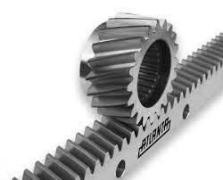
Rack and pinion drive systems use a linear gear (rack) and a circular gear (pinion) to convert the motor’s rotary motion into linear motion. As the pinion rotates, it engages the teeth on the rack, creating linear movement.
Pros:
Scalability: Rack and pinion systems can be easily scaled to accommodate a wide range of CNC router sizes and configurations, making them suitable for both small and large machines.
High-Speed Performance: Rack and pinion systems can operate at high speeds due to their efficient conversion of rotary motion to linear motion, reducing job completion times and increasing productivity.
Durability: Rack and pinion systems are known for their durability, as the gear teeth are designed to withstand high levels of stress and wear, ensuring a longer service life for your CNC router.
Cons:
Backlash: Rack and pinion systems can have more backlash than ballscrew systems, which may affect the precision and accuracy of the CNC router.
Noise: Rack and pinion systems can be noisier than ballscrew systems due to the contact between the gear teeth.
Maintenance: The teeth on the rack and pinion need to be properly lubricated and maintained to ensure smooth operation and prevent wear.
Modern Industrial CNC Routers Compensation
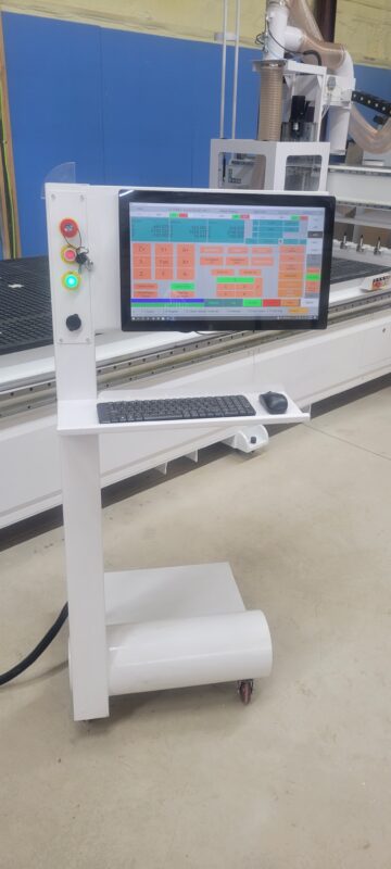
At Front Range CNC we utilize both rack and pinion or ball screw on all 3 axes and the decision between which drive system lies primarily in your application and needs. We only use industrial controllers and this allows us to tune our CNC routers using advanced algorithms to further diminish backlash and compensation on both drive systems. Learn how each of our three industrial control options deal with backlash and compensation.
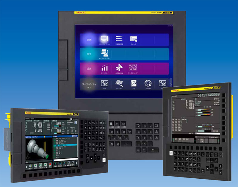
The Fanuc 0i-MF is a versatile CNC controller that is widely used in various machining applications. To compensate for backlash, the Fanuc 0i-MF employs a software-based backlash compensation technique, which is commonly found in CNC controllers.

Here’s how the Fanuc 0i-MF compensates for backlash:
Measurement and Configuration: The first step is to measure the backlash value for each axis in the mechanical system. This can be done using a dial indicator or another suitable measuring device. Once the backlash values are known, they need to be entered into the Fanuc 0i-MF’s parameters. In the Fanuc 0i-MF, backlash compensation parameters are typically found in the ‘Backlash Compensation’ section of the parameter list, denoted by the parameter numbers 1850 to 1855 (X, Y, Z, 4th, 5th, and 6th axes).
Backlash Compensation Activation: After configuring the backlash values, the Fanuc 0i-MF’s backlash compensation feature must be activated. To do this, the user enables the backlash compensation function in the controller settings. This is typically done by setting a specific bit in the corresponding parameter (usually parameter 2400).
Compensation during Motion: With backlash compensation activated, the Fanuc 0i-MF takes the backlash value into account when generating motion commands. When the direction of an axis changes, the controller adds or subtracts the corresponding backlash value from the position setpoint before initiating movement in the new direction. This action compensates for the backlash and ensures that the position of the machine remains accurate.
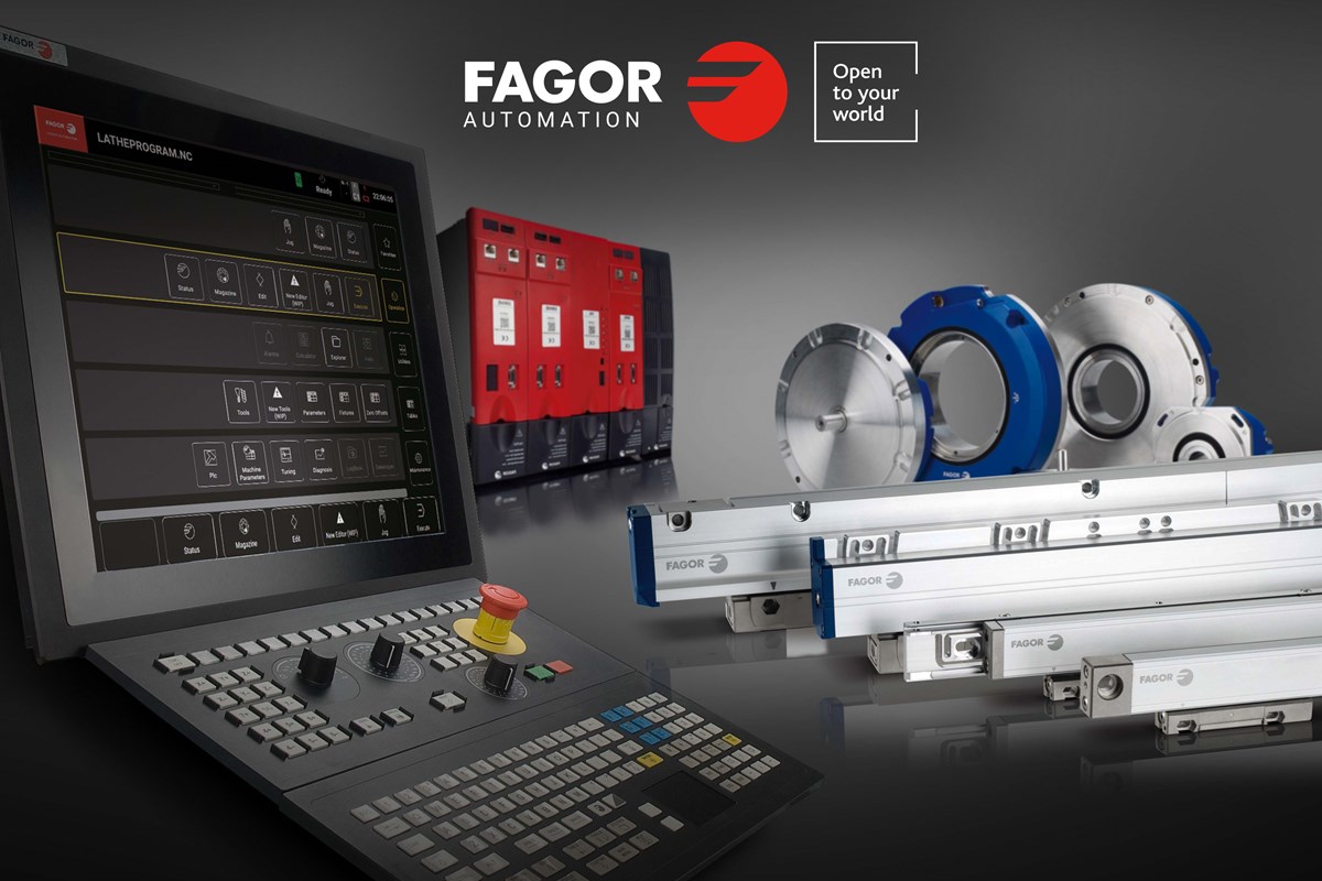
Here is how the Fagor 8058 compensates for backlash:

The Fagor 8058 is a CNC controller used for various machining applications. To compensate for backlash, the Fagor 8058 uses a software-based backlash compensation method, which is a commonly employed technique in CNC controllers.
Here’s how the Fagor 8058 compensates for backlash:
Measurement and Configuration: First, the backlash value for each axis must be determined. This value can be obtained by measuring the actual backlash in the mechanical system using a dial indicator or another suitable measuring device. Once the backlash values are known, they can be entered into the Fagor 8058’s parameters.
Backlash Compensation Activation: After configuring the backlash values, the Fagor 8058’s backlash compensation feature can be activated. To do this, the user enables the backlash compensation function in the controller settings.
Compensation during Motion: With backlash compensation activated, the Fagor 8058 takes the backlash value into account when generating motion commands. When the direction of an axis changes, the controller adds or subtracts the corresponding backlash value from the position setpoint before initiating movement in the new direction. This action compensates for the backlash and ensures that the position of the machine remains accurate.
Here’s how the Syntec 21MA handles backlash compensation:

Measurement and Configuration: The first step is to measure the backlash value for each axis in the mechanical system. This can be done using a dial indicator or another suitable measuring device. Once the backlash values are known, they need to be entered into the Syntec 21MA’s parameters. In the Syntec 21MA controller, backlash compensation values are typically entered in the “Pulse Equivalent & Backlash Compensation” section of the parameter settings.
Backlash Compensation Activation: After configuring the backlash values, the Syntec 21MA’s backlash compensation feature must be activated. To do this, the user enables the backlash compensation function in the controller settings. This is typically done by setting the backlash compensation activation parameter to “1” (enabled).
Compensation during Motion: With backlash compensation activated, the Syntec 21MA takes the backlash value into account when generating motion commands. When the direction of an axis changes, the controller adds or subtracts the corresponding backlash value from the position setpoint before initiating movement in the new direction. This action compensates for the backlash and ensures that the position of the machine remains accurate.
